
A standpipe flow test proves the system can deliver its required flow and residual pressure at the hydraulically most remote hose valve. Classify the system first (Class I, II, or III), then set gauges, open valves gradually, record pitot and residual readings, and restore the system to service. Do this on the five-year NFPA 25 interval. Verify against the adopted edition.
Every year, fire protection contractors across Virginia and Maryland face the challenge of keeping standpipe systems in top working order while meeting demanding compliance checks. The stakes are high, since efficient standpipe flow testing not only supports NFPA standards but also guarantees system readiness for life safety. This guide breaks down a clear workflow that covers system classification, preparation, safe equipment setup, step-by-step testing, and post-test procedures, giving you a proven path to accurate results and strong documentation.
A flow test is the only thing that proves your standpipe will actually deliver water at the right pressure when a firefighter opens a valve.
Step 1: Review and Prepare the Standpipe System for Testing
Preparing a standpipe system for flow testing requires systematic verification of multiple critical components to ensure safety and compliance with NFPA standards. Your goal in this initial stage is to comprehensively inspect and validate all system elements before initiating the actual testing procedure.
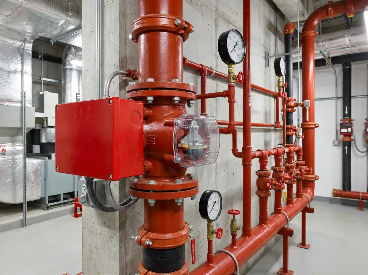
Start by reviewing the standpipe system classification to determine specific testing requirements (NFPA 14 §5.3). Understanding whether your system is Class I, II, or III, and whether it is wet, dry, or manual, directly impacts your testing protocol. Key preparation steps include:
- Verify all gate valves and connection points are accessible.
- Check hose lengths and coupling compatibility.
- Ensure fire pump systems are fully operational.
- Review recent maintenance records.
- Confirm all safety personnel are notified about upcoming testing.
Carefully document the current system status, including initial static and residual pressure readings. These baseline measurements will be crucial for comparing performance during the actual flow test. Pay special attention to any signs of corrosion, valve stiffness, or potential obstruction that might compromise system performance, the same hidden issues a trip test and pipe flushing is designed to clear.
The three main standpipe classes differ in purpose: Class I systems use large 2½-inch outlets for fire department use, Class II systems use smaller hoses intended for occupant use, and Class III systems combine both, requiring testing protocols that address each equipment type (NFPA 14 §5.3).
Pro tip: Schedule your standpipe system inspection at least one week before the planned flow test to allow time for any necessary repairs or adjustments.
Step 2: Install Test Equipment and Ensure Safety Measures
Installing test equipment for a standpipe flow test requires precision, careful planning, and strict adherence to safety protocols. Your primary objective is to set up measurement devices and protective measures that enable an accurate and safe testing procedure.
Begin by implementing critical safety protocols, including lockout/tagout procedures for all control valves. Identify and notify all relevant safety personnel about the upcoming test, and ensure they are present and prepared. Equipment installation requires meticulous attention to detail:
- Position pressure gauges at strategic points.
- Attach appropriate hose lengths with proper restraints.
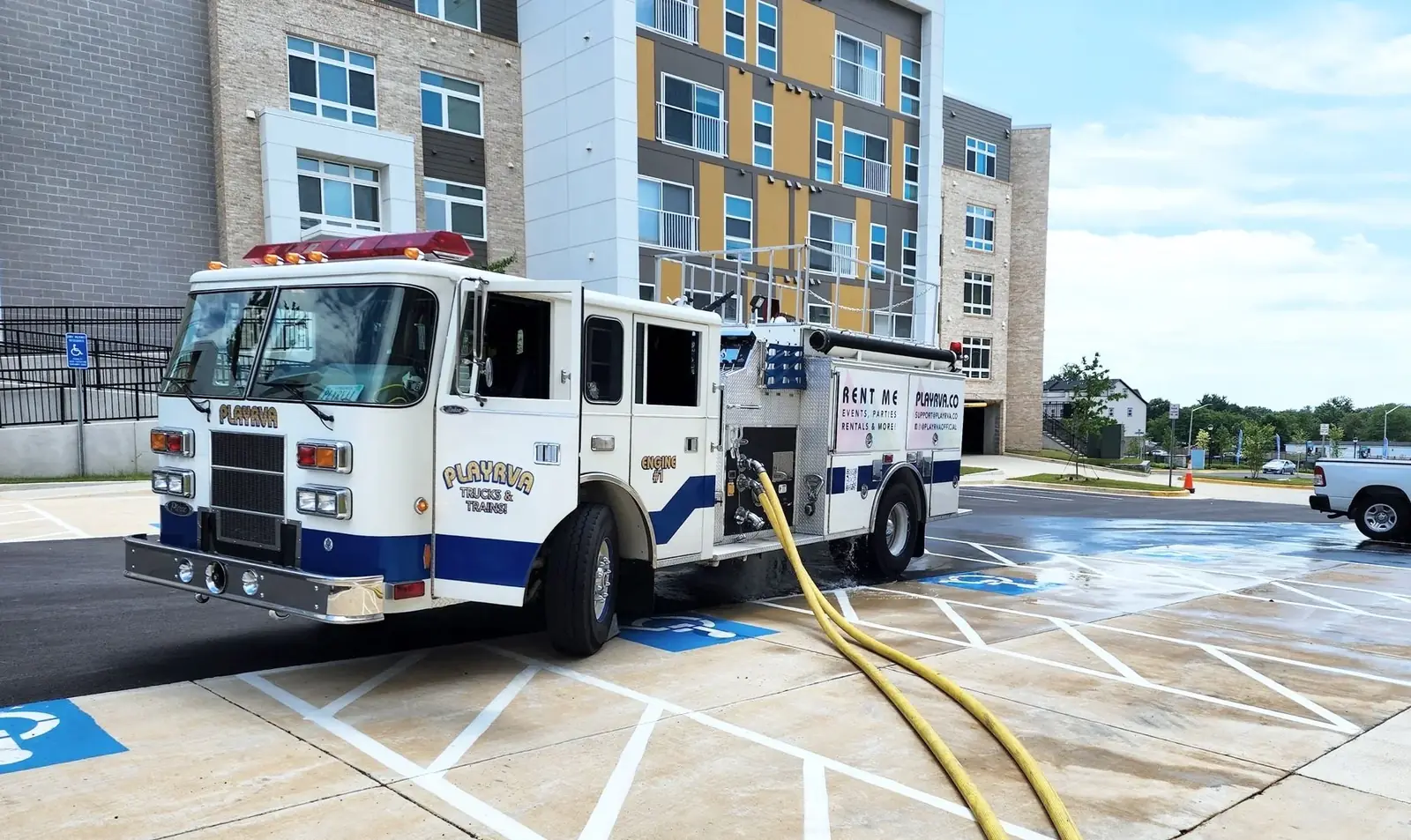
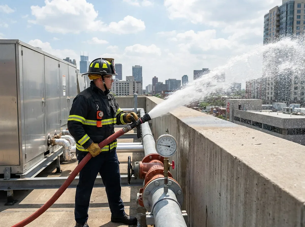
- Use 3-inch hoses to direct water flow safely away from building structures.
- Place pitot gauges at hose ends for precise flow measurement.
- Confirm fire pump operational status.
Your test setup must prevent potential water damage while maintaining safe distances for operators. Proper gauge placement and secure hose connections are critical to collecting accurate data and maintaining personnel safety.
Safety and precision are the cornerstones of an effective standpipe flow test.
Pro tip: Always conduct a preliminary equipment check and have backup measurement tools available to mitigate potential testing interruptions.
Step 3: Open Valves and Initiate the Flow Test Procedure
Initiating the standpipe flow test requires a systematic approach to valve operation and pressure monitoring. Your goal is to carefully activate the system while collecting precise hydraulic performance data without causing unnecessary stress to the infrastructure.
Begin by removing outlet caps and bleeding air from the standpipe system using petcock valves. This critical preparation step ensures accurate pressure readings and prevents potential measurement errors. Follow these key procedural steps:
- Remove protective caps from test outlets.
- Use petcock valves to eliminate air from the lines.
- Take initial static pressure readings.
- Open isolation and test connection valves gradually.
- Maintain consistent water flow for stable measurements.
- Monitor pressure at multiple standpipe outlets.
Carefully control the valve opening process to prevent sudden pressure surges. Gradual valve activation allows for precise data collection and minimizes potential system stress. Observe pressure gauges continuously during the test, watching for any unexpected fluctuations that might indicate underlying system issues.
Pro tip: Always have a communication plan in place with all team members to quickly respond to any unexpected pressure changes or equipment anomalies during testing.
Step 4: Record Flow Rates and System Pressures Accurately
Capturing precise measurements during a standpipe flow test is critical for evaluating system performance and maintaining fire protection infrastructure. Your objective is to document hydraulic data with scientific rigor and complete compliance with industry standards.
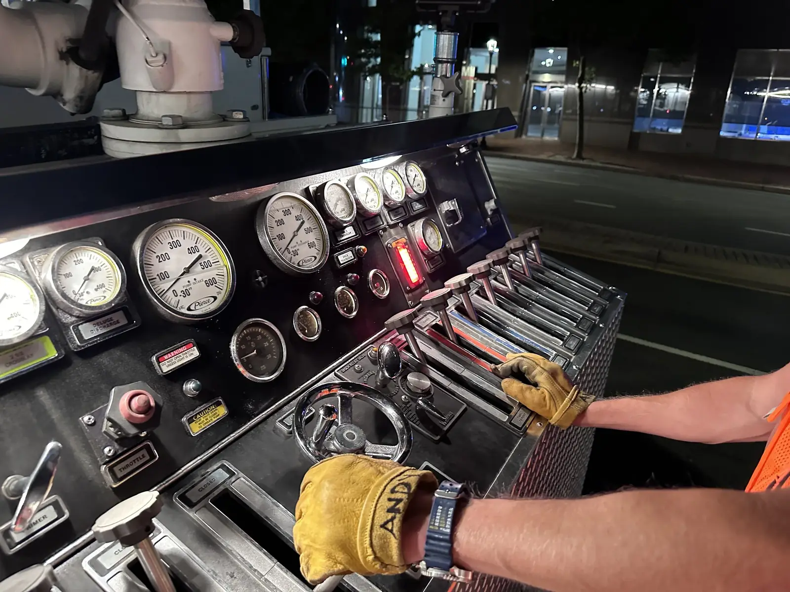
Begin by utilizing calibrated measuring instruments for recording flow rates and system pressures. A static gauge captures initial and residual pressure at the system riser, a pitot gauge measures velocity pressure and flow rate at the hose end during discharge, and a cap gauge records static pressure at the discharge outlet. Methodical documentation requires:
- Use pitot gauges to measure velocity pressure.
- Attach cap gauges for static and residual pressure readings.
- Record exact pressure values at multiple discharge points.
- Document hose size and orifice dimensions.
- Note environmental testing conditions.
- Capture real-time pressure fluctuations.
Each measurement must be meticulously logged on standardized test sheets. Comprehensive data collection ensures future reference and validates the standpipe system's operational integrity. Cross-reference your readings against established NFPA performance benchmarks (NFPA 14 §7.8 residual pressure, commonly 100 psi at the most remote 2½-inch Class I/III outlet; NFPA 14 §7.10 flow rates; NFPA 14 §11.5 at acceptance vs NFPA 25 §6.3.1 for periodic tests). Convert pitot readings with the hydrant flow test calculator when you are measuring from a hose stream. Verify those design figures against the adopted edition, and remember the water supply behind the system matters too, which is why a fire hydrant flow test often runs alongside standpipe testing.
Precision in measurement translates directly to reliability in fire protection systems.
Pro tip: Always use duplicate recording methods and have a backup data collection system to prevent potential information loss during critical testing.
Step 5: Verify Test Results and Restore the System to Service
The final stage of standpipe flow testing involves comprehensive result verification and systematically returning the system to full operational status. Your objective is to ensure the standpipe system meets all performance standards and is immediately ready for emergency response.
Post-test system restoration requires meticulous attention to detail and adherence to NFPA guidelines. Follow these critical steps to complete the process:
- Compare recorded pressures with design specifications.
- Close all test valves carefully.
- Replace protective outlet caps.
- Shut down temporary fire pump configurations.
- Remove fire alarm system bypasses.
- Check for any potential leaks or system anomalies.
- Notify relevant public safety personnel.
Thoroughly document all test results and observations. Comprehensive reporting is essential for maintaining compliance and providing a clear record of the system's performance, the same paper trail that protects you at claim time, as we explain in Insurance Won't Cover What You Didn't Maintain. Any deviations from expected performance standards should trigger immediate further investigation and potential system maintenance.
Pro tip: Create a standardized checklist for post-test procedures to minimize the risk of overlooking critical restoration steps.
Ensure NFPA Compliance with Expert Standpipe Flow Testing
Conducting a standpipe flow test for NFPA compliance requires precision, thorough preparation, and accurate data collection. The challenges of managing valve operations, measuring flow rates, and verifying system pressures can lead to costly delays or failed inspections if not handled correctly. You need a trusted partner who understands the technical details, static and residual pressure, pitot gauge readings, and proper valve sequencing, to avoid damaging your system or risking safety.
We specialize in professional standpipe flow tests, hydrostatic pressure tests, and hydrant flow tests tailored to meet NFPA 14 and NFPA 25 standards. Whether you are a fire protection contractor, property manager, or building developer, our services help you pass critical inspections without disruption. Don't risk costly downtime or safety gaps, request a quote today and guarantee compliance and safety for your fire protection system.